555 Timer Bike Turn Signal
Fall 2023
555 Timer project developed for Junior Design
Inspiration
I often go on bike rides during the summer as a form of exercise, as well as a mode of transportation during the school year. While riding to class one day, I removed one of my hands from the handlebars while slowing towards an intersection, and hit a bump that send me tumbling off the bike. While riding a bicycle on a road, one is supposed to remove a hand from the handlebars in order to indicate turning. This made me think: “What if bikes had turn signals, just like cars?”
Circuit Design
While personally relevant, the idea for a Bike Turn Signal was not original to me. A user on Circuit Digest named Saddam had posted an example of a breadboarded circuit to achieve this result, which can be found here. This design served as a great starting point for me, though I ended up making some modifications.
First, the circuit was duplicated to enable conditions for both right and left turn signals. To match, two momentary push buttons to be mounted on the handlebars were implemented to trigger each circuit. Then, I added two more 9V batteries to improve the system’s battery life. The single color LEDs were replaced with RGB LEDs, as well as a switch to change them between being blue and yellow to improve visibility for different conditions.
Now for the technical details: This circuit is driven by a 555 timer implemented in the astable configuration. This produces a periodic squarewave output that feeds into a series of NPN transistors that trigger each other sequentially, with a delay between each implemented via an RC circuit. Each transistor outputs to one of the RGB LEDs. Thus, the system illuminates sequentially in the direction that the user is turning.

Circuit simulated in LTSpice for verification

Output results from LTSpice simulated circuit

Breadboard test prior to PCB design

Full Altium schematic
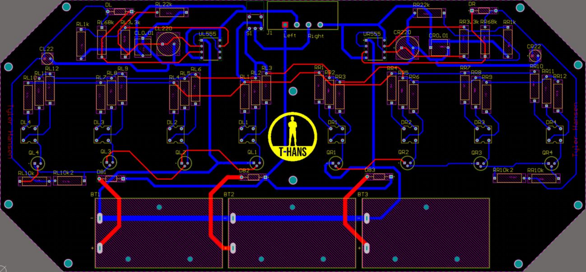
Final PCB design

Final assembly

Final assembly (top view)
Key Takeaways
PCB design using Altium Designer
Component selection
PCB troubleshooting and alteration
Parallel battery protection